The Story of a Norton Commando Racing Motorcycle Rebuild
Part 5
February 2003
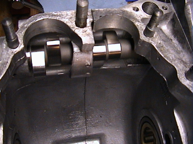
Installing a crankshaft should be a straightforward job. However, because I was fitting a much bumpier high-lift racing camshaft, it was certainly not that simple.
The camshaft tunnels in the 1970 engine cases had to be bored out to make room for the bigger lobes of the camshaft.
Fortunately the camshaft bushes in the cases were in good shape, with correct clearances, so I did not have to remove and replace them, which requires specialized machinery.
Once the cam was fitted, I proceeded to assemble the connecting rods onto the crankshaft. Be sure to torque those bolts. Applying some red locktite is a great idea too.
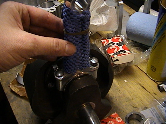
It is important to measure the end float of the crankshaft. This is the movement back and forth in the bearings that is allowed. On a Norton Commando it should be between 5 thousands to 11 thousands of an inch. There are thin shims that are used to shim it tighter. I used two of those shims to give a measured end float of 7 thousandths of an inch.
Then it is time to put the new racing pistons onto the con rods. I found it helpful to freeze the pins to make them slide more easily into the pistons and little-ends of the connecting rods. Note the new cylinder head studs that Aiden and I fitted into the block.

I made up a jig out of wood from a template in one of my many Norton workshop manuals. This allows one to hold the pistons and con rods vertically while lowering the freshly bored cylinders down. Be sure to use appropriate piston ring clamps.... trying to accomplish this without them is a recipie for broken rings. And when you have to mount the barrel 5 times (more anon), it's truly a neccessity.
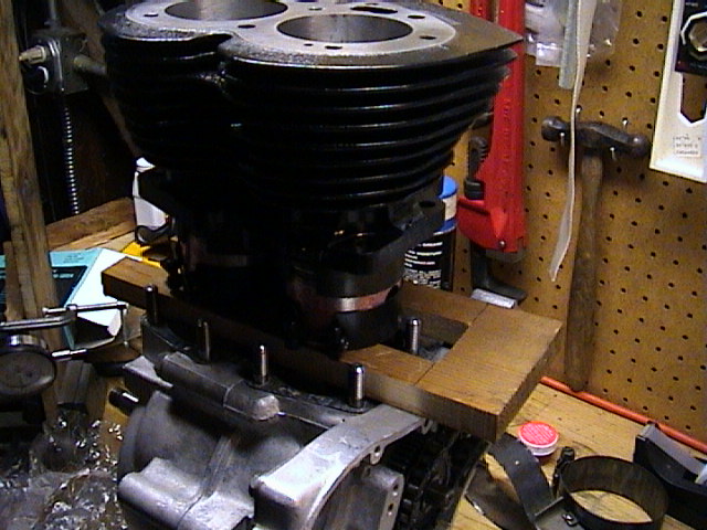
The cyliners were bored to 0.040 larger, and appropriate racing pistons were sourced. Don't they look sharp in their fresh bores? It's almost a shame to subject them to internal combustion!
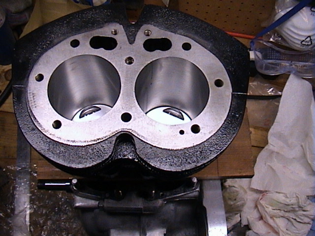
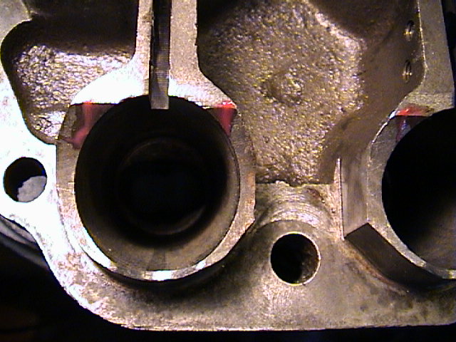
I torqued down the cylinder to the values specified in the Norton Villiers workshop manual. And it was at this point that I discovered that I was not finished with fitting the camshaft!!! You see, it seems that the bigger lobes interfered with the tappet tunnels in the cylinder block when it is fully torqued down. By using red camshaft engine assembly lube, I was able to determine where the camshafts were hitting the tappet tunnels. You can see the red goo on the edges of the tunnels below.
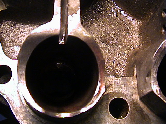
And now you can see where my trusty Dremel tool was used to machine away the metal to give clearance for the cam lobes.
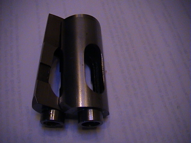
Well, after going back and forth and re-installing the cylinder 5 times, I got it all right. I could then lube up and insert the new tappets. The tappets (cam followers) had to be machined from the standard flat to a 3" radius to accomodate the high lift of the camshaft.
I also fitted a set of new hollow lightweight racing pushrods.
Funny how a job that should have taken a few hours took about 4 days....